
While the S in IoT stands for "security", the T stands for "things", and things move. Wouldn't it be nice to know how they move, exactly?
Gyroscopes & Gimbals
A lot of manufactures have started putting gyroscopes into most everything. When you pair up 3 gyroscopes on each of the 3 real-world axes, you can start to understand how an object pivots around a point. With some advanced processing, these motion processors can keep track of the absolute position (relative to a calibrated start point), instead of just reporting "turning left for 3 seconds..."
i2c
While some of previous experiments worked with USART (serial ports) and SPI (another serial port), our chosen motion processing chip uses the i2c bus, which again is sorta a serial port.
Unlike SPI, though, where we used a physical signal to select a chip for communications, with i2c, every device on the bus has its own address. Within a transaction, you address bytes to a device, and while the transaction is open, you can read bytes from the device.
The content across the i2c bus is pretty device-specific, but there are some commonly-seen conventions.
Registers
A lot of what occurs in the embedded world deals with registers, which are 1-to-4 (or more) bytes of addressable memory. Many i2c devices work with the same concept, allowing you to read and write values within registers on the device.
To read a an imaginary register (0xAB), which can be addressed by a 1-byte address, and returns a 1-byte value:
// to hold the response returned
let mut response = [0; 1];

// write the address of the register to read, to the device to read from
i2c.read( device_address, [ 0xAB ], &mut response )
To write an imaginary register (0xAB), which can be addressed by a 1-byte address, with a 1-byte value (0x42):
i2c.write( device_address, [ 0xAB, 0x42 ] );
The device's reference manual should describe the registers and their values. As usual, many registers are bitfields, so you may have to read a register's and toggle specific bits within it before writing it back to the device.
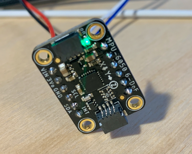
The MPU-6050
The InvenSense/TDK MPU-6050 is a small motion processor with 3 gyroscopes and matching accelerometers. For this post, we will only be exploring how to make the gyroscopes track movement.
Raw Data
The easiest data to retrieve from the MPU-6050 is raw data from the gyroscopes and accelerometers, which is provided in relative terms. You can gain the degrees-per-time or G-forces-per-time for each axis at a given point in time. To consume these values though, you have to do a fair bit of math and bookkeeping on your own.
DMP Data
The MPU-6050 includes a digital motion processor (DMP). Ultimately, the entire MPU-6050 has its own MCU on-board and runs its own firmware. To take advantage of the DMP, though, you must load, after each power-up, the DMP firmware. Our Rust driver helps you out with that.
The benefit of using the DMP is that the chip provides for the math and bookkeeping, providing you with a series of quaternions on a FIFO. A quaternion involves math significantly beyond my own comprehension, but the bottom line is that they represent an absolute rotation/position of the chip. A quaternion is a set of 4 numbers, which uniquely identify how the item is rotated around each of its axes.
Visualizing
The three.js project provides a set of tools for working in three dimensional scenes within the browser. Even more importantly, it also works with quaternions. If we can connect the data being pumped from the MPU-6050 to the browser, then the physical motion process can replace two-dimension controls such as a mouse or trackpad.
Let's Rust
Since this is an i2c device, first we have to set up a typical i2c bus, however is appropriate for your board.
For my board, after patching the HAL to support i2c3:
let scl3 = gpioc.pc0.into_open_drain_output(&mut gpioc.moder, &mut gpioc.otyper)
                    .into_af4(&mut gpioc.moder, &mut gpioc.afrl);

let sda3 = gpioc.pc1.into_open_drain_output(&mut gpioc.moder, &mut gpioc.otyper)
                    .into_af4(&mut gpioc.moder, &mut gpioc.afrl);

let i2c = I2c::i2c3(device.I2C3, (scl3, sda3), KiloHertz(100), clocks, &mut rcc.apb1r1);
Next we create an instance of the MPU-6050 driver attached to that i2c.
Notice, we're using an embedded-time-based Clock as described in a previous post.
let sensor = Mpu6050::new(i2c, Address::default(), &CLOCK).unwrap();
It can have one of two predetermined i2c addresses, based on if an extra connection is made. We're using the default address.
We stuff that into our RTIC shared resources, and pick it up later, in our idle task once the clock is ticking forward.
Use the Sensor
Since we want to have to think less about math, we initialize_dmp() to ensure the chip is ready to do our bidding with absolute positioning information:
let sensor: &mut Mpu6050<'_, _, _> = ctx.resources.sensor;
sensor.initialize_dmp().unwrap();
Now, all the important information will be heading towards us through a FIFO, in 28-byte packets. You can drive reading the FIFO from an interrupt if you prefer, but here we're running in a simple loop. As long as there's at least one packet of 28 bytes available, we read it out:
loop {
    let len = sensor.get_fifo_count().unwrap();
    if len >= 28 {
        let mut buf = [0; 28];
        let buf = sensor.read_fifo(&mut buf).unwrap();
         ...
    }
}
Now that you have a [u8;28] of bytes, knowing how the packet is constructed is helpful.
Today, we will use the knowledge that the first 16 bytes are the quaternion in (w, x, y, z) format, 4 bytes for each portion.
We can either feed that to the Quaternion::from_bytes(...) to use it on-board, or we can shuffle it straightaway unprocessed to the visualizer.
We choose the second option in this case.
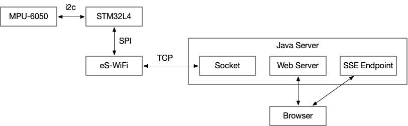
Tie it all together
Hopefully this post has helped see how we can tie together a bag of disparate drivers, protocols, technologies and languages into a single functioning system.
The crate to accomplish all of this from the embedded side is drogue-mpu-6050 and it is available on crates.io.