
There's a lot of variety in the embedded world. While we've implemented the ESP8266 WiFi-offload board over USART last time, now we're doing the Inventek eS-WiFi over the SPI bus. Let's explore some of the differences.
eS-WiFi
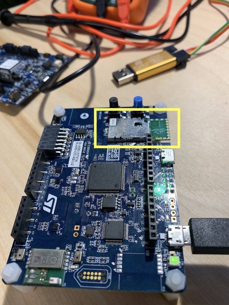
The reason we're addressing this WiFi-offload board is because it's what ships on the STM B-L4S5I-IOT01A board. Radio-related peripherals are often sold as complete units and soldered onto another board, instead of built natively onto the main board from components. This assists with certifications from the FCC and other bodies that care about the signals you're emitting.
As with the ESP8266, it ostensibly uses Hayes AT commands to communicate. Unlike the ESP8266, the eS-WiFi, at least when mounted by STM onto this devboard, uses SPI as it's interface.
SPI
SPI is a unique little beast. It's a bus, which allows multiple peripherals to be attached at a time. You may see abbreviations such as MISO and MOSI, but given sensitivity of the underlying words and how they affect others, we're moving to using CIPO and COPI.
CIPO stands for Controller In, Peripheral Out, which COPI stands for Controller Out, Peripheral In.
Two wires; one heads each direction.
Additionally, there's a SCK wire, which provides a clock (driven by the controller), so there is no need to agree a-priori on the communication speed. (This assumes the peripheral can keep up with the speed set by the controller). Compare to USARTs, where both sides have to agree, out-of-band, on the baudrate, etc.
With multiple peripherals on the bus, the way each peripheral is given a chance to talk to the controller is through a chip select (CS) pin. In general, the controller dedicates one pin per peripheral. These pins are active low, so that to signal a chip is selected, the pin should be brought down to ground. This also means you need either an internal or external pull-up resistor so that when the peripheral is not selected, it's seeing a positive voltage on its end of the CS wire.
Given that there are two roles (controller and peripheral), this indicates that any communication that occurs is at the behest and control of the controller, hence it's name and role. Periphals cannot just random start transmitting. The controller will lower a given a peripheral's CS pin to signal that communications is desired with it.
And then things get weird.
Even when selected, the peripheral doesn't drive the clock (SCK), so it still can't communicate.
Instead, the bus works with simultaneous bi-direction communication, driven by the controller. For every byte the controller sends, the peripheral sends a byte. Of course, on the face of it, this makes it seem like the controller and peripheral both shout at each other for the same amount of time.
In reality, the controller may communicate something (like a request) to the peripheral, and ignore the junk that the peripheral is shouting back at the same time. Then, in order to receive a response that includes useful content, the controller will continue to send additional junk to the peripheral (which it ignores) so that it can swap bytes back to the controller. This is sometimes referred to "clocking out bytes". The bytes sent by the control in this mode are pretty meaningless, other than defining the clock pulses that the peripheral can use to return data.
How does the controller know how much junk to send to give the peripheral a chance to fully reply?
In some cases, the on-the-wire protocol may define, thought a reference document, how many bytes to expect. Or the protocol may involve some number of bytes which encode a length of the remainder of the payload. In the case of the eS-WiFi board, there yet another pin, the ready pin, which is controlled by the peripheral. As long as the peripheral keeps that pin high, the controller continues to transmit junk, and gather the response bytes from the peripheral. Once that pin goes low, the controller can stop pumping out junk bytes and know it has the entire response.
Word up.
The HAL for the STM32L4 implements a 8-bit-word-based SPI interface. The eS-WiFi board uses 16-bit words (or roughly... 2 bytes).
Unfortunately, a 16-bit word is not exactly a straight-line array of two 8-bit bytes.
Reading bytes
The eS-Wifi communication involves swapping bytes, if you read in two 8-bit bytes in at a time. And to read bytes, you have to transmit junk, but in this case, very specific junk: newline bytes.
Here, we transmit 2 newlines, and the SPI will replace those two characters with two bytes of the peripheral's response (which it actually sent as a single 16-bit word):
let mut xfer: [u8; 2] = [0x0A, 0x0A];
let result = self.spi.transfer(&mut xfer);
Given the 8-vs-16 bit wordsize and byte-swapping, we have to read the array backwards. The data should be interpreted in this order:
let buffer: [u8;2 ] = [ xfer[1], xfer[0] ]
If, by chance, we were working with larger arrays of transfers, we'd have to read each pairwise set of bytes in swapped order.
In an 8-array, we'd have to interpret the data using indices: 1 0 3 2 5 4 7 and then 6.
The eS-WiFi will also send an 0x15 (nak) if it doesn't want to transmit an even number of bytes, as padding.
Writing bytes
Just as with reading, the controller has to deal with byte-swapping and padding, but in this case, we must pad with 0x0A (newline) if we don't have an even number of bytes.
for chunk in command.chunks(2) {
    let mut xfer: [u8; 2] = [0; 2];
    xfer[1] = chunk[0];
    if chunk.len() == 2 {
        xfer[0] = chunk[1]
    } else {
        xfer[0] = 0x0A
    }

    let result = self.spi.transfer(&mut xfer);

    ...
}
Effectively, if we wanted to transmit ['b', 'o', 'b'], we would have to transmit two 2-byte arrays shaped like:
[ 'o', 'b' ]
[ '\n', 'b' ]
Or as a 4-array: [ 'o', 'b', '\n', 'b']
Fun, yeah?
But now you can TCP
Of course, all of this gets hidden, as it's implementation details for the driver.
See the drogue-es-wifi crate's README for details on how to use it to actually do some TCP connections.